

If you work in the oil and gas industry dealing with offshore drilling, corrosion is your worst enemy. A corroded oil platform is a dangerous platform and it can cost you a lot — in both lives and money. To avoid such a dark fate, you need to safeguard the steel structure from corrosion via a protection system, such as the cathodic protection process shown here.
Corrosion Protection for Oil Platforms
There are several ways you can protect structures from corrosion: Impressed Cathodic Current Protection (ICCP), anodic protection, and by using sacrificial anodes. We will prescribe the third method in this example.
About the Sacrificial Anodes Protection Method
The sacrificial anodes method essentially involves protecting the cathode by sacrificing the anode. In the case of oil platforms, the steel structure is what needs protecting. Therefore, we can turn the steel into the cathode by connecting it electronically to a metal that is less noble, i.e. anodic (such as aluminum, for example).
When the electrodes are then immersed in seawater, the less noble metal will be polarized anodically and the steel structure will be polarized cathodically. The metal anodes will undergo anodic dissolution. Meanwhile, oxygen reduction will occur at the steel structure’s surface.
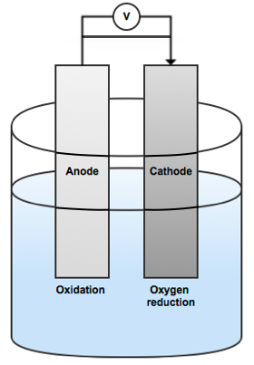
Simplified illustration of the anode and cathode polarization.
The current density for oxygen reduction is commonly limited by the oxygen supply. This results in a near-constant, transport-limited current for a range of potential difference at the structure’s surface, spanning a few hundred millivolts.
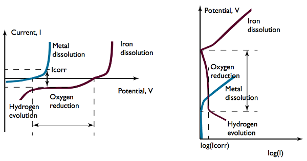
Polarization: Sacrificial anodes (blue) and steel surface (red).
If you look at the graphs above, see where it says “Oxygen reduction”? The dashed lines on either side of that label indicate that when current flows, the sacrificial anodic dissolution (blue line) and cathodic oxygen reduction (red line) currents are equal in size. Note that the exact shape of the blue polarization curve is determined by the accessibility and number of anodes.
Design Considerations
In order to fully protect the structure, design engineers need to make sure the oil platform’s various parts are safely within the corrosion-protected range. In other words, the voltage delivered by the anodes needs to be sufficient to drive oxygen reduction at the steel to balance the current. You also have to take care to avoid hydrogen evolution, as that could cause hydrogen embrittlement. During the process, increased pH may lead to formation of a calcareous film at the cathode surface, which changes the conductivity at the surface. The growth of these deposits can also be accounted for in high-fidelity models.
When designing your cathodic protection system, you will first need to figure out the potential difference between the steel structure and the seawater during oxygen reduction. Doing so, you can determine what part will be more vulnerable to corrosion — before it’s too late. This is where the Corrosion Module comes in handy.
Results from Modeling Corrosion Protection
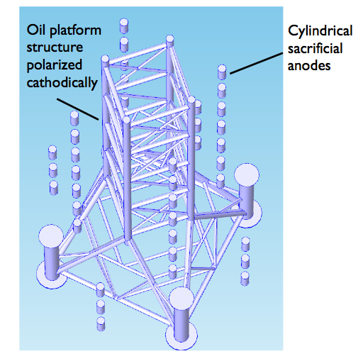
Suppose we polarize the oil platform cathodically and place cylindrical sacrificial anodes in the structure’s proximity.
Instead of detailing exactly how to set up and solve the model, let’s skip ahead to the results.
You can learn how to build the model by downloading the documentation from the Model Gallery or opening the model from within the Model Library in the Corrosion Module (under the “Cathodic Protection” section).
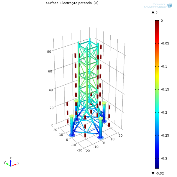
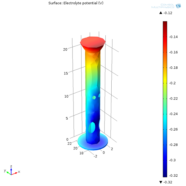
First, let’s examine the electrolyte potential at the oil platform’s surface as well as on the anodes. From the surface plot, we can see that the further away the protected structure is from the sacrificial anodes, the lower the potential in the electrolyte (seawater). The lower the electrolyte potential at the interface, the more positive the potential difference is between the oil platform and seawater. The more prone a structure is to oxidation, the less protected it will be. Naturally, we need to make sure that we always distribute sacrificial anodes well, so that the entire structure is protected.
Next, we can have a look at the electrolyte potential in one of the oil platform legs. The inside bottom section of the leg has the lowest electrolyte potential (most anodic interfacial potential difference) and will therefore be more prone to corrosion.
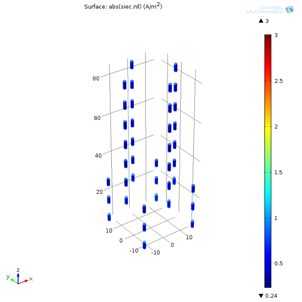
Finally, we can plot the current densities on the anodes. This is important because the magnitude of the current densities is directly proportional to the anode metal’s consumption rate. In other words, this can help us determine how long the sacrificial anodes will last.
Now that we’ve gone through this introduction to modeling corrosion for the oil and gas industry, why don’t you try out the model yourself? Once you’ve built it, you could try moving around the anodes or even adding some more to “retrofit” the structure.
Suggested Resources
- Model download: Oil Platform Corrosion Protection Using Sacrificial Anodes
- Learn about current distribution


Comments (0)