

Over the years, the development of sensor technology has enabled more accurate measurements of fluid flow. One such device is the thermal flow sensor. This instrument is valued for its simple design and implementation as well as its high degree of accuracy. Using COMSOL Multiphysics, a team of researchers from the University of Cambridge designed a 3D model to analyze the dynamics of a thermal flow sensor, a component of a flow meter.
The Roots of Thermal Flow Sensing Technology
Introduced by L.V. King in 1914, the hot-wire anemometer represented the first of its kind: A device that could measure fluid flow using thermal sensing techniques. In a hot-wire anemometer, a thin wire is electrically heated to a temperature greater than its surroundings. The surrounding flow cools down the device up to a given temperature. Because of the known relationship between the electrical resistance of the wire and its temperature, the fluid velocity can be obtained from the knowledge of the wire’s resistance.
Because of their delicate nature, hot-wire anemometers are often not suitable for industrial use as many applications include dirt, which can cause damage to these fragile devices. Hot-wire anemometers are also referred to as intrusive devices, because the sensors do not only measure the flow properties, but they also disrupt the flow. A more viable solution in such cases would be to use a thermal mass flow meter. The thermal mass flow meter is a non-intrusive device, i.e., it leaves the flow path unobstructed. While applying the same concepts as their predecessor, these instruments feature casing around the wires, enhancing their durability as well as their accuracy in measuring fluid flow.

A schematic of a thermal mass flow meter.
Thermal mass flow meters have been used extensively for measurement in gas flow applications, from thermal transfer to chemical reactions. These instruments are particularly favored in the industry for their simplistic design, as there are no moving parts included in the device.
A team from the University of Cambridge used COMSOL Multiphysics software to develop a 3D model of thermal flow sensors and analyze the dynamics behind the components’ operation. Let’s explore how simulation enabled this team to describe the behavior of this instrument under every physical aspect.
Solving a 3D Model of a Thermal Mass Flow Sensor
The design of the model used in the study was based on a silicon on insulator (SOI), complementary metal-oxide semiconductor (CMOS) MEMS thermal flow sensor — or SOI CMOS MEMS thermal flow sensor, for short. The model features a validation chip that includes five parallel metal strips. The strip in the center is used to increase the temperature of the device to 300°C. All of the strips can be used to sense the temperature through the relationship between the metal resistivity and the absolute temperature. A four-wire measurement is used to obtain the resistance value.
When developing this validation chip, deep reactive ion etching was implemented at the back surface to remove the silicon substrate from beneath the sensing elements. This postprocessing step drastically reduced the thermal conductivity observed by the heating element and, consequently, lowered the power required to increase the temperature at the desired value.
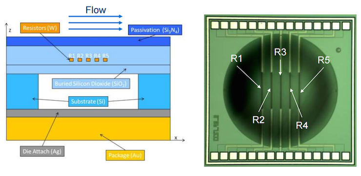
The geometry of the thermal flow sensor. The image on the left shows the cross-sectional view of the validation device, while the image on the right shows the top view. Image by C. Falco, A. De Luca, S. Sarfraz, and F. Udrea, and taken from their COMSOL Conference 2014 Cambridge paper submission.
In their analysis, the research team coupled three different physical domains — electric current, heat transfer in solids, and laminar flow — to create a multiphysics model. That is, the bias current is used to locally heat up the component, through the Joule heating effect, and conductive and convective heat transfer dissipate the excess heat.
Comparing Simulation Results with Experimental Data
Initially, the flow sensor was validated in still air. The plot below represents a validation of the relationship between dissipated power in the heater and the temperature sensed by alternate resistors without flow above the surface. The values from the simulation and the experiment are shown to mirror one another.
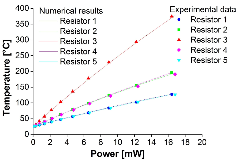
Comparing the temperature in all the resistors within the simulation and experimental data. Image by C. Falco, A. De Luca, S. Sarfraz, and F. Udrea, and taken from their poster submission.
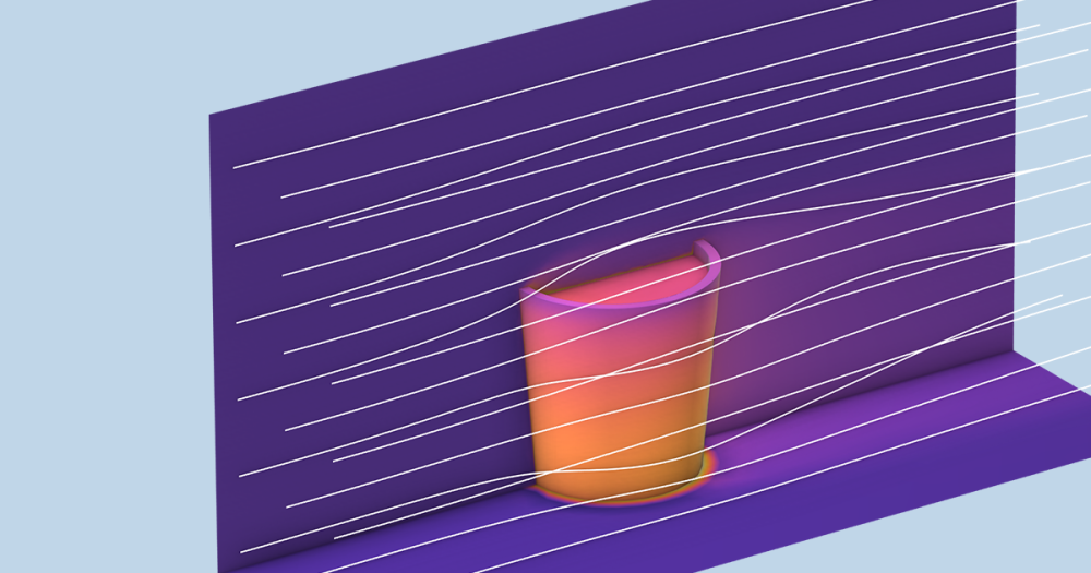
The figure below provides a complete temperature profile for the current value of 10 mA.
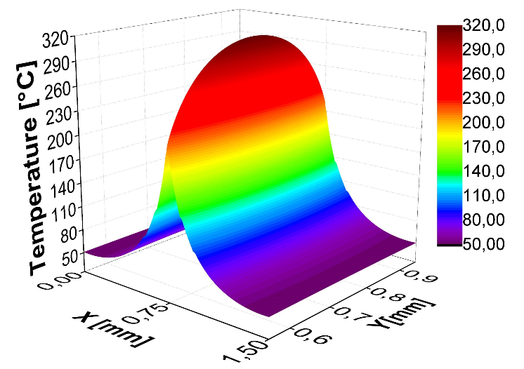
Temperature profile in the area of interest. Image by C. Falco, A. De Luca, S. Sarfraz, and F. Udrea, and taken from their poster submission.
The wall shear stress, defined as the stress that a viscous fluid exerts on a wall, is chosen to characterize the fluid properties. In the next step, the research team calibrated the sensor, with the air movement above the chip included in the analysis, for varying values of wall shear stress. Comparing three values for the biasing current (6, 8.5, and 10 mA), the results showed good agreement between the temperature within the resistors and the experimental data for wall shear stress.
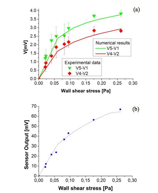
Plots depicting the sensor output as a function of wall shear stress. The graph on the top (a) shows the calorimetric approach and the graph on the bottom (b) represents the anemometric approach. An anemometric approach involves the measurement of the changes in the voltage across the heater; the calorimetric approach senses the variance in voltage between resistors that are placed symmetrically on opposing sides of the heater. Image by C. Falco, A. De Luca, S. Sarfraz, and F. Udrea, and taken from their paper submission.
Summary
Here, we have introduced research designed to investigate the behavior of thermal flow sensors. Coupling heat transfer, electric current, and laminar flow, the simulation provides accurate predictions of the sensor’s behavior and, by modifying the model’s geometry and material properties, can be applied to various applications of this technology. With its high precision and range of applications, the thermal flow sensor model serves as a powerful resource in optimizing the design of thermal flow sensors and developing prototypes more efficiently.
Download the Research
- Access the paper, presentation, poster, and abstract as presented at the COMSOL Conference 2014 Cambridge: “3D Multiphysics Model of Thermal Flow Sensors“


Comments (2)
SAIKUMAR PATTABIRAMAN
October 29, 2015Dear Researcher,
I’m a postgraduate student working for my master thesis on fluid flow and velocity measurement using thermal method.
i had designed the sensor and i can’t able to make my structure for temperature sensing and to power up the heater to a constant temperature level. This is based on the calorimetric principle method.
my project is based on intrusive method.
So kindly guide and help to complete my thesis work.
I will be a thankful if you reply for the post.
Regards,
SAIKUMAR
EMAIL ID: saikumar.p2014@vit.ac.in
Skype ID: saikumarpattabiraman
Bridget Cunningham
October 29, 2015Hi Saikumar,
Thank you for your comment. If you have specific questions pertaining to your simulations, please contact your COMSOL support team so they can help you.
Online support center: https://www.comsol.co.in/support
Email: support@comsol.com