
How can you use an electric field to control the movement of electrically neutral particles? This may sound impossible, but in this blog entry, we will see that the phenomenon of dielectrophoresis (DEP) can do the trick. We will learn how DEP can be applied to particle separation and demonstrate a very easy-to-use biomedical simulation app that is created with the Application Builder and run with COMSOL Server™.
Forces on a Particle in an Inhomogeneous Static Electric Field
The dielectrophoretic effect will show up in both DC and AC fields. Let’s first look at the DC case.
Consider a dielectric particle immersed in a fluid. Furthermore, assume that there is an external static (DC) electric field applied to the fluid-particle system. The particle will in this case always be pulled from a region of weak electric field to a region of strong electric field, provided the permittivity of the particle is higher than that of the surrounding fluid. If the permittivity of the particle is lower than the surrounding fluid, then the opposite is true; the particle is drawn to a region of weak electric field. These effects are known as positive dielectrophoresis (pDEP) and negative dielectrophoresis (nDEP), respectively.
The pictures below illustrate these two cases with a couple important quantities visualized:
- Electric field
- Maxwell stress tensor (surface force density)
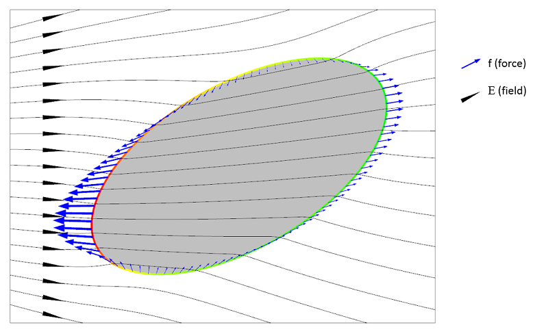
An illustration of positive dielectrophoresis (pDEP), where the particle permittivity is higher than that of the surrounding fluid \epsilon_p > \epsilon_f.
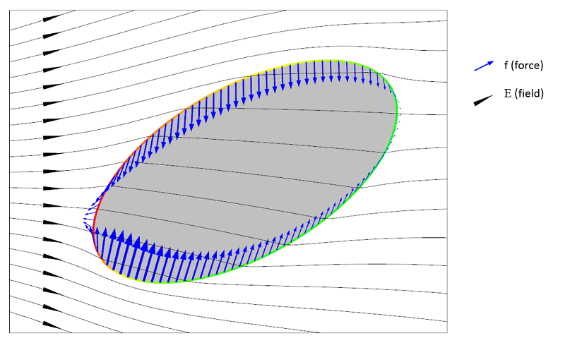
An illustration of negative dielectrophoresis (nDEP), where the particle permittivity is lower than that of the surrounding fluid \epsilon_p < \epsilon_f.
The Maxwell stress tensor represents the local force field on the surface of the particle. For this stress tensor to be representative of what forces are acting on the particle, the fluid needs to be “simple” in that it shouldn’t behave too weirdly either mechanically or electrically. Assuming the fluid is simple, we can see from the above illustrations that the net force on the particle appears to be in opposite directions between the two cases of pDEP and nDEP. Integrating the surface forces will indeed show that this is the case.
It turns out that if we shrink the particle and look at the infinitesimal case of a very small particle acting like a dipole in a fluid, then the net force is a function of the gradient of the square of the electric field.
Why is the net force behaving like this? To understand this, let’s look at what happens at a point on the surface of the particle. At such a point, the magnitude of the electric surface force density, f, is a function of charge times electric field:
(1)
where \rho is the induced polarization charges. (Let’s ignore for the moment that some quantities are vectors and make a purely phenomenological argument by just looking at magnitudes and proportionality.)
The induced polarization charges are proportional to the electric field:
(2)
Combining these two, we get:
(3)
But this is just the local surface force density at one point at the surface. In order to get a net force from all these surface force contributions at the various points on the surface, there needs to be a difference in force magnitude between one side of the particle and the other. This is why the net force, \bf{F}, is proportional to the gradient of the square of the electric field norm:
(4)
In the above derivation, we have taken some shortcuts. For example, what is the permittivity in this relationship? Is it that of the particle or that of the fluid or maybe the difference of the two? What about the shape of the particle? Is there a shape factor?
Let’s now address some of these questions.
Force on a Spherical Particle
In a more stringent derivation, we instead use the vector-valued relationship for the force on an electric dipole:
(5)
where \bf{P} is the electric dipole moment of the particle.
To get the force for different particles, we simply insert various expressions for the electric dipole moment. In this expression, we can also see that if the electric field is uniform, we get no force (since the particle is small, its dipole moment is considered a constant). For a spherical dielectric particle with a (small) radius r_p in an electric field, the dipole moment is:
(6)
where k is a parameter that depends on the the permittivity of the particle and the surrounding fluid. The factor 4 \pi r_p^3 can be seen as a shape factor.
Combining these, we get:
(7)
This again shows the dependency on the gradient of the square of the magnitude of the electric field.
Forces on a Particle in a Time-Varying Electric Field
If the electric field is time-varying (AC), the situation is a bit more complicated. Let’s also assume that there are losses that are represented by an electric conductivity, \sigma. The dielectrophoretic net force, \bf{F}, on a spherical particle turns out to be:
(8)
where
(9)
and
(10)
is the complex-valued permittivity. The subscripts p and f represent the particle and the fluid, respectively. The radius of the particle is r_p and \bf{E}_{\textrm{rms}} is the root-mean-square of the electric field. The frequency of the AC field is \nu.
From this expression, we can get the force for the electrostatic case by setting \sigma = 0. (We cannot take the limit when the frequency goes to zero, since the conductivity has no meaning in electrostatics.)
In the expression for the DEP force, we can see that indeed the difference in permittivity between the fluid and the particle plays an important role. If the sign of this difference switches, then the force direction is flipped. The factor k involving the difference and sum of permittivity values is known as the complex Clausius-Mossotti function and you can read more about it here. This function encodes the frequency dependency of the DEP force.
If the particles are not spherical but, say, ellipsoidal, then you use another proportionality factor. There are also well-known DEP force expressions for the case where the particle has one or more thin outer shells with different permittivity values, such as in the case of biological cells. The simulation app presented below includes the permittivity of the cell membrane, which is represented as a shell.
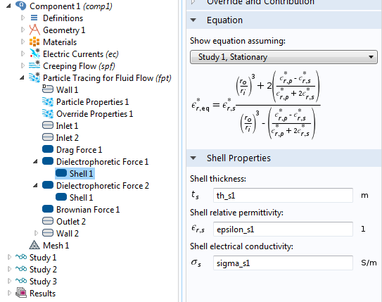
The settings window for the effective DEP permittivity of a dielectric shell.
There may be other forces acting on the particles, such as fluid drag force, gravitation, Brownian motion force, and electrostatic force. The simulation app shown below includes force contributions from drag, Brownian motion, and DEP. In the Particle Tracing Module, a range of possible particle forces are available as built-in options and we don’t need to be bothered with typing in lengthy force expressions. The figure below shows the available forces in the Particle Tracing for Fluid Flow interface.
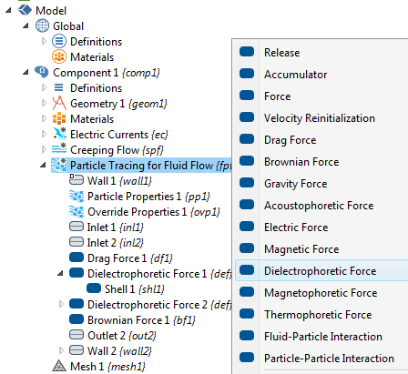
The different particle force options in the Particle Tracing for Fluid Flow interface.
Dielectrophoretic Separation of Particles
Medical analysis and diagnostics on smartphones is about to undergo rapid growth. We can imagine that, in the future, a smartphone can work in conjunction with a piece of hardware that can sample and analyze blood.
Let’s envision a case where this type of analysis can be divided into three steps:
- Extract blood using the hardware, which attaches directly to your smartphone, and compute mean platelet and red blood cell diameter.
- Compute the efficiency of separation of the red blood cells and platelets. This efficiency needs to be high in order to perform further diagnostics on the isolated red blood cells.
- Use the computed optimum separation conditions to isolate the red blood cells using the hardware attached to your smartphone.
The COMSOL Multiphysics simulation app focuses on Step 2 of the overall analysis process above. By exploiting the fact that blood platelets are the smallest cells in blood and have different permittivity and conductivity than red blood cells, it is possible to use DEP for size-based fractionation of blood; in other words, to separate red blood cells from platelets.
Red blood cells are the most common type of blood cell and the vertebrate organism’s principal means of delivering oxygen (O2) to the body tissues via the blood flow through the circulatory system. Platelets, also called thrombocytes, are blood cells whose function is to stop bleeding.
Using the Application Builder, we created an app that demonstrates the continuous separation of platelets from red blood cells (RBCs) using the Dielectrophoretic Force feature available in the Particle Tracing for Fluid Flow interface. (The app also requires one of the following: the CFD Module, Microfluidics Module, or Subsurface Flow Module and either the MEMS Module or AC/DC Module.)
The app is based on a lab-on-a-chip (LOC) device described in detail in a paper by N. Piacentini et al., “Separation of platelets from other blood cells in continuous-flow by dielectrophoresis field-flow-fractionation”, from Biomicrofluidics, vol. 5, 034122, 2011.
The device consists of two inlets, two outlets, and a separation region. In the separation region, there is an arrangement of electrodes of alternating polarity that controls the particle trajectories. The electrodes create the nonuniform electric field needed for utilizing the dielectrophoretic effect. The figure below shows the geometry of the model.
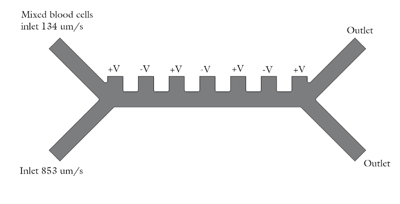
The geometry used in the particle separation simulation app.
The inlet velocity for the lower inlet is significantly higher (853 μm/s) than the upper inlet (154 μm/s) in order to focus all the injected particles toward the upper outlet.
The app is built on a model that uses the following physics interfaces:
- Creeping Flow (Microfluidics Module) to model the fluid flow.
- Electric Currents (AC/DC or MEMS Module) to model the electric field in the microchannel.
- Particle Tracing for Fluid Flow (Particle Tracing Module) to compute the trajectories of RBCs and platelets under the influence of drag and dielectrophoretic forces and subjected to Brownian motion.
Three studies are used in the underlying model:
- Study 1 solves for the steady-state fluid dynamics and frequency domain (AC) electric potential with a frequency of 100 kHz.
- Study 2 uses a Time Dependent study step, which utilizes the solution from Study 1 and estimates the particle trajectories without the dielectrophoretic force. In this study, all particles (platelets and RBCs) are focused to the same outlet.
- Study 3 is a second Time Dependent study that includes the effect of the dielectrophoretic force.
You can download the model that the app was based on here.
A Biomedical Simulation App
To create the simulation app, we used the Application Builder, which is included in COMSOL Multiphysics® version 5.0 for the Windows® operating system.
The figure below shows the app as it looks like when first started. In this case, we have connected to a COMSOL Server™ installation in order to run the COMSOL Multiphysics app in a standard web browser.
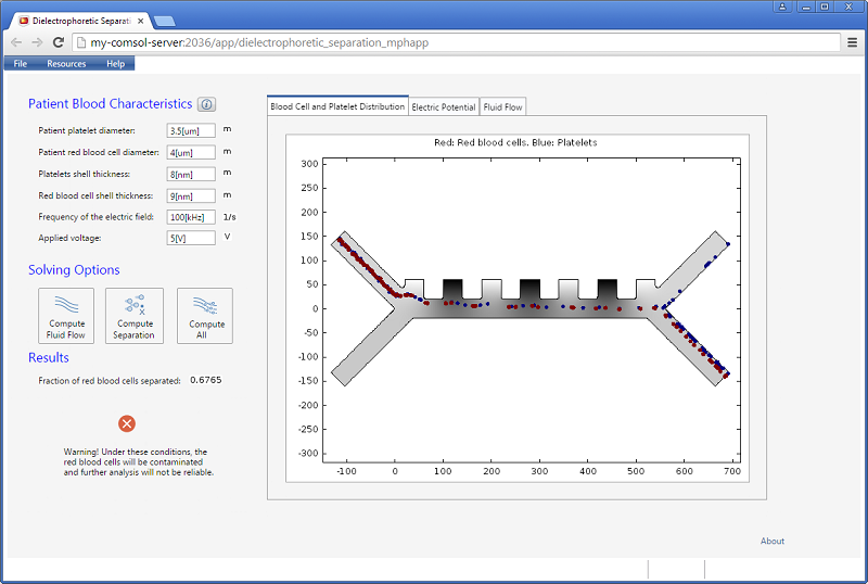
A biomedical simulation app running in a standard web browser.
The app lets the user enter quantities, such as the frequency of the electric field and the applied voltage. The results include a scalar value for the fraction of red blood cells separated. In addition, three different visualizations are available in a tabbed window: the blood cell and platelet distribution, the electric potential, and the velocity field for the fluid flow.
The figures below show visualizations of the electric potential and the flow field.
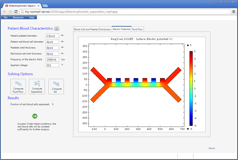
Screenshot showing the instantaneous electric potential in the microfluidic channel.
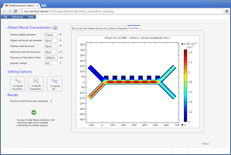
Screenshot displaying the magnitude of the fluid velocity.
The app has three different solving options for computing just the flow field, computing just the separation using the existing flow field, or combining the two. A warning message is shown if there is not a clean separation.
Increasing the applied voltage will increase the magnitude of the DEP force. If the separation efficiency isn’t high enough, we can increase the voltage and click on the Compute All button, since in this case, both the fields and particle trajectories need to be recomputed. We can control the value of the Clausius-Mossotti function of the DEP force expression by changing the frequency. It turns out that at the specified frequency of 100 kHz, only red blood cells will exit the lower outlet.
The fluid permittivity is in this case higher than that of the particles and both the platelets and the red blood cells experience a negative DEP force, but with different magnitude. To get a successful overall design, we need to balance the DEP forces relative to the forces from fluid drag and Brownian motion. The figure below shows a simulation with input parameters that result in a 100% success in separating out the red blood cells through the lower outlet.
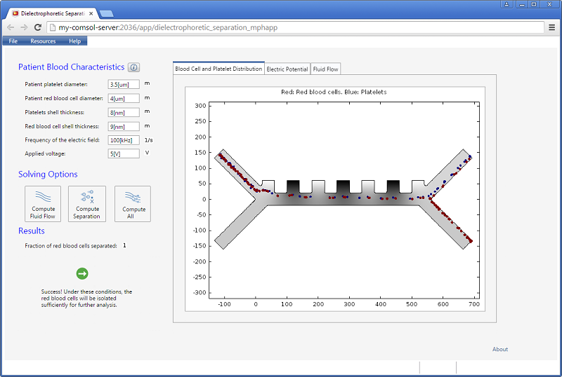
Successful separation of red blood cells.
Further Reading
To learn more about dielectrophoresis and its applications, click on one of the links listed below. Included in the list is a link to a video on the Application Builder, which also shows you how to deploy applications with COMSOL Server™.
- Model Gallery: Dielectrophoretic Particle Separation
- Video Gallery: How to Build and Run Simulation Apps with COMSOL Server™ (archived webinar)
- Wikipedia: Dielectrophoresis
- Wikipedia: Maxwell-Wagner-Sillars polarization
- Wikipedia: Clausius-Mossotti relation
Windows is either a registered trademark or trademark of Microsoft Corporation in the United States and/or other countries.



Comments (11)
Kelvin Zhao
October 13, 2016Dear Bjorn
As I’m doing the simulation of particle separation with DC-DEP by Particle Tracing Module. I have a question about the data setting of the CM factor.
When using DC electric field, the CM factor could be expressed as f_CM=((σ_p-σ_m)/(σ_p+2σ_m )). In this way, the CM factor becomes only related with the conductivity of the suspending medium and the particle, and as long as we know the electrical conductivity, the CM factor is determined.
However, in the Particle Tracing Module, the CM factor cannot directly be inputted or expressed in this way and is always related with dielectric constant, electrical conductivity and frequency, which is suitable for AC-DEP.
Therefore, when DC electric field is used and the CM factor is only related to the electrical conductivity, how to input or set these data for CM factor?
Looking forward to your reply!
Best
Kelvin Zhao, Ph.D. Student
Department of Mechanical and Mechatronics
University of Waterloo
Bridget Cunningham
October 20, 2016Hello Kelvin,
Thank you for your comment.
For questions related to your modeling, please contact our support team.
Online support center: https://www.comsol.com/support
Email: support@comsol.com
Best,
Bridget
osman Şahin
April 9, 2018Hi,
When I made dielectrophoresis simulation in 4.3 version with Comsol, I could not select Shell property which is one of the necessities from Particle Tracing for Fluid Flow. How can I solve the problem?
In addition to previous mail, without selecting cell module, when I made simulation, I got following error message;
Failed to evaluate variable Jacobian. – Variable: mod1.ec.Ey – Geometry: 1 – Domain: 2 Failed to evaluate operator Jacobian. – Operator: env_pgeom_fpt – Geometry: 2 – Boundary: 1 Failed to evaluate operator Jacobian. – Operator: env_pgeom_fpt – Geometry: 2 – Boundary: 1
I could not interprent concepts of the message which are Geometry, Boundary and Operator.
Thank you.
Caty Fairclough
April 9, 2018Hi Osman,
Thanks for your comment.
For your question, I would suggest contacting our Support team.
Online Support Center: https://www.comsol.com/support
Email: support@comsol.com
Vivek Boominathan
July 22, 2018Hi Team,
Can I separate particles in the nanometer ranges? Say for example if I need to separate a particle that is about 50nm from a particle about 200nm. Please let me know your thoughts.
Thanks,
mostafa69 aghdasi69
September 7, 2018hi.
i want to simulate motion of two particles by dielectrophoresis but i can not exert dielectrophoresis force to particles.particles suspended in fluid media and all domain are in electic field. i think for this i should calculate maxwell stress tensor on particles. i use FSI and electric current modules. can you help me??? my particles are large and i cant use particle tracing module.
Caty Fairclough
September 7, 2018Hi there,
Thanks for your interest in this blog post.
For your questions, I would suggest contacting our Support team.
Online Support Center: https://www.comsol.com/support
Email: support@comsol.com
志亮 韩
January 9, 2020In physics, particles have volume and mass,Whether you can add repulsion between particles to prevent particles from overlapping?
Brianne Christopher
January 13, 2020Hello 志亮 韩,
Thank you for your comment.
For questions related to your modeling, please contact our Support team.
Online Support Center: https://www.comsol.com/support
Email: support@comsol.com
Beh Arz
November 2, 2021Hi
In this simulation to model the electric field you have used to electric potential port (+v) and (-v), why did you use two electric potentials instead of ground and an electric potential?
Thanks
Bjorn Sjodin
November 2, 2021 COMSOL EmployeeHi Beh Arz,
Yes, this is an arbitrary choice and it would work just as well with ground and an electric potential.
Best regards,
Bjorn