

Piezoelectric devices are widely used as sources to generate sound waves or receivers to detect acoustic signals. In applications such as ultrasound imaging and nondestructive testing, the same transducer can be used as a transmitter to send a source signal and receiver to detect echoes. Modeling these devices often requires transient analyses with time of flight as output. Let’s discuss how to use the COMSOL Multiphysics® software to model a piezoelectric device as both a transmitter and receiver.
Connecting a Transducer to an External Circuit in a Piezoelectric Device
The best way to model a piezoelectric device that acts as both a transmitter and receiver is to connect the transducer to an external circuit using the Terminal feature. This is usually the situation in real-life applications in which a piezoelectric layer is sandwiched between two thin electrode layers so that it can be connected to a circuit. An additional benefit of the Terminal feature is that COMSOL Multiphysics calculates the available lumped parameters, which can be evaluated after the model is solved.
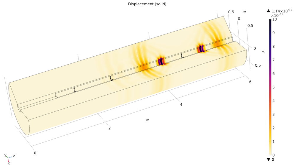
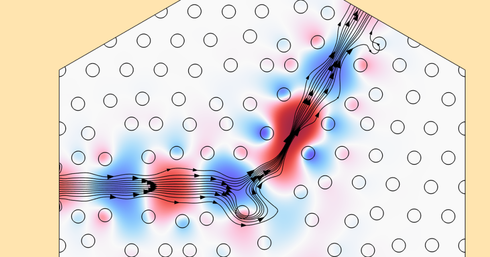
A model of a sonic well logging setup with a piezoelectric transducer that transmits and receives sound.
The Terminal feature and Electric Circuit interface are available with the AC/DC Module or MEMS Module. An alternate method is to use the Surface Charge Density feature and specify the surface charge to excite the transducer. (This will be discussed later in the blog post.)
Using the Terminal Feature
To demonstrate, we are going to set up a simple 2D axisymmetric model of a piezoelectric device. As illustrated in the figure below, a lead zirconate titanate (PZT-5H) disc of 2 mm in radius and 1 mm in thickness is used as a transducer. It sits in an infinitely large baffle and radiates a sound pulse to the water domain above. When the sound waves reach the rigid walls on the top, they are reflected back to the water domain and picked up by the transducer. The acoustic energy is both reflected back toward the receiver, but some is also transmitted out of the domain.
This process will repeat many times before the acoustic energy is diminished by scattering or attenuation. The water domain is assumed to extend to infinity in the lateral direction, which is modeled using the Perfectly Matched Layer (PML) feature.
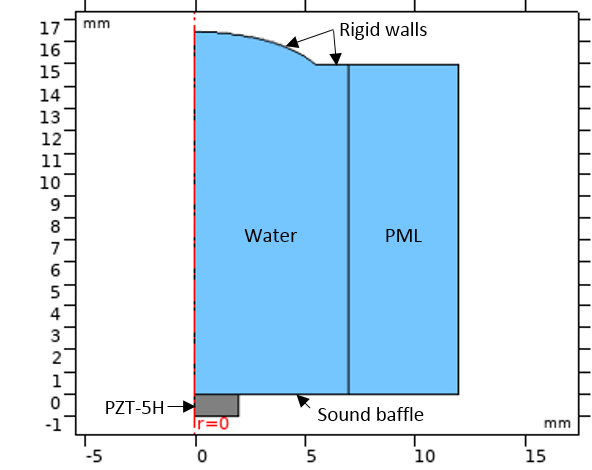
The geometry of the model for demonstration.
This scenario can be modeled using the Acoustic-Piezoelectric Interaction, Transient interface, a predefined multiphysics interface that combines the Pressure Acoustics, Transient and Piezoelectric Devices interfaces to couple the acoustic pressure variations in the fluids to the structural deformation in both the solids and piezoelectric solid domains. The Piezoelectric Devices interface is also a multiphysics interface. It combines the Solid Mechanics and Electrostatics interfaces together with the constitutive relationships required to model piezoelectricity.
When using the Terminal feature, an Electrical Circuit interface is added to the model to excite the transducer and receive detected signals. A graphic representation of the circuit is shown on the left in the figure below. The excitation pulse generated by the voltage source is a Gaussian-shaped modulated sine wave of central frequency 200 kHz (shown on the right.)
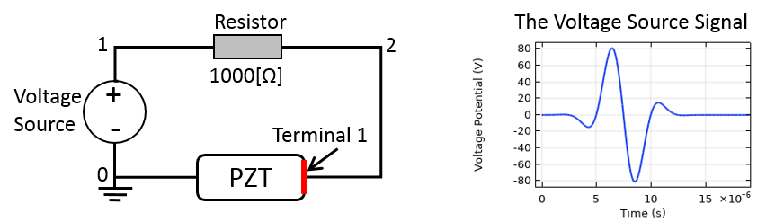
An electrical circuit is connected to a transducer to drive the device and receive signals. The excitation electrical pulse is shown on the right.
To connect the transducer to the electrical circuit in the model, you need to:
- Add a Terminal node to the Electrostatics interface and set the Terminal type to Circuit (top image)
- The Terminal node provides a current-voltage characteristic to the circuit
- On the boundary selection, add the boundary where the electrode is connected to the electrical circuit
- In this example, it’s the top surface of the piezo device
- Add a Ground node to the Electrostatics interface and apply it to the other electrode of the piezo device (center image)
- In this example, the bottom surface of the piezo device is grounded
- Add an External I-Terminal node to the Electrical Circuit interface and set the electrical potential of the external terminal to Terminal voltage (es/term1) (bottom image)
- The External I-Terminal feature connects a voltage-to-ground measurement as a voltage-to-ground assignment to a node in the electrical circuit
- The resulting circuit current from the node is then coupled back as a prescribed current source in the context of the voltage measurement
- In the Node Connections edit field, make sure the correct node is entered (in this example, it is node 2, as indicated above)
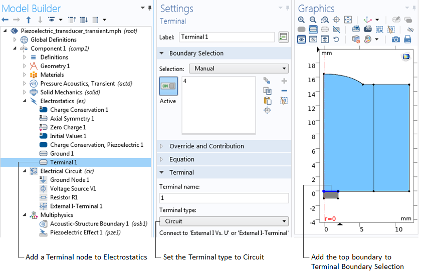
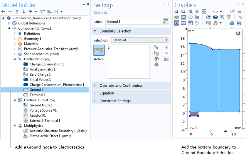

Connecting the transducer to the electrical circuit using a Terminal feature.
Below, the acoustic pressure is plotted at the centerpoint of the top surface of the transducer. The model is solved for up to 13 acoustic cycles to capture the first 2 echoes that reach the transducer. This information is also included in the terminal voltage received by the electric circuit, as shown in the bottom image below, where the signals from the first and second echoes are zoomed in for a better visualization.
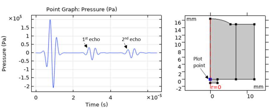
A plot of the acoustic pressure at the centerpoint of the top surface of the transducer.
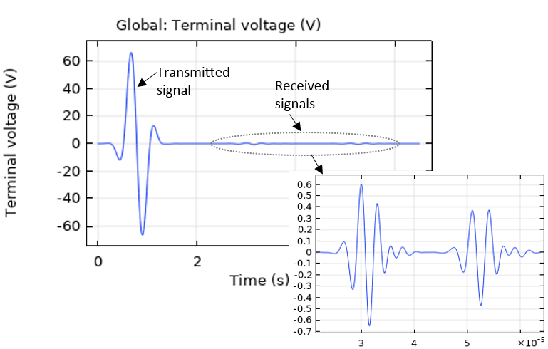
A plot of the terminal voltage that can be measured by the electrical circuit.
Using the Surface Charge Density Feature
If you do not have access to the Terminal feature, you can use the Surface Charge Density feature instead. Surface Charge Density is a boundary condition that can be added to the Electrostatics interface and applied to the electrode surface of the transducer.

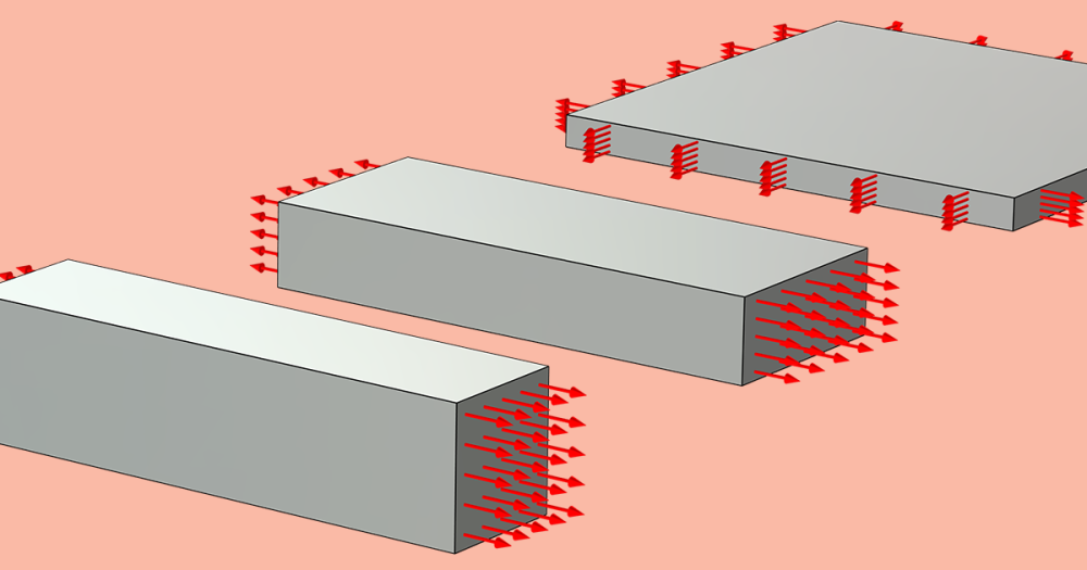
Using the Surface Charge Density feature to model the transducer.
In general, you can use the Terminal feature or the Surface Charge Density feature to model a transducer as a transmitter, a receiver, or both at the same time. When a transducer is only used as a transmitter and you do not intend to use it to detect any incoming back signals, an Electric Potential node can also be used to specify the electric potential on the excitation surface. On the other hand, to model a transducer as a receiver only, a Floating Potential feature can be used as well. The Floating Potential node is used when modeling a metallic electrode at floating potential. When the charge is set to zero, the boundary will behave as an unconnected, neutrally charged, good conductor under electrostatic conditions.
Try It Yourself
In the Sonic Well Logging tutorial model, you can use the Terminal feature with an electric circuit to model the transmitter, which is also used as a receiver. The other two receivers used in the model are simulated using the Floating Potential feature.
Click the button below to access the documentation and MPH-file for the sonic well logging model:

Comments (16)
Ahmad Muttaqi
March 9, 2019Hello thanks for the tutorial it is very helpful. However, may I know:
1. The expression for terminal voltage
2. The study used. (Time Dependent or Frequency Domain)
Jinlan Huang
March 11, 2019Hi Ahmad,
The model is actually available for download in the application gallery: https://www.comsol.com/model/modeling-piezoelectric-devices-as-both-transmitters-and-receivers-71111. It uses a time dependent study, and you can find the expression for the voltage source in the Electrical Circuit physics.
Ahmad Muttaqi
March 14, 2019Hi Jinlan,
Thank you for your response. That was really helpful for me especially by referring the model you gave.
Ahmad Muttaqi
April 23, 2019Hi Jinlan,
Sorry for disturbing but may I ask if the size of transducers is matters? If yes, may I know why?
Thank you.
cha ohrum
July 3, 2019i have a one question.
The wall and the distance are about 16 mm. Why is this attenuation so much?
Bohua Zhang
August 13, 2019How can I change the voltage source Gaussian-shaped modulated sine wave into a square wave pulse?
Jinlan Huang
August 15, 2019Hi Cha,
Only a fraction of the acoustic energy reaches the other side and comes back to the transducer. Most are scattered away and lost to the PML domain which represents an extension of the water domain to infinity.
Jinlan Huang
August 15, 2019Hi Bohua,
You can use a Rectangle function to define a square wave pulse. Make sure smoothing is applied to ramp up and down the load as described in the following support knowledge base: https://www.comsol.com/support/knowledgebase/1244/.
Ceez ben
April 26, 2020hi, I simply want to know did you do a time dependent, modal analysis or time dependent one?
Jinlan Huang
April 28, 2020 COMSOL EmployeeHi Ceez, the example used in this blog solves a transient model because the excitation signal is a pulse. The model can be downloaded at the link here: https://www.comsol.com/model/modeling-piezoelectric-devices-as-both-transmitters-and-receivers-71111.
priyesh pandey
July 27, 2020can i get steps to develops this model?
yash kumar dhabi
September 16, 2020Hi Jinlan,
Thank you for the blog post.
I am trying to use the same transducer for application in NDT, for a concrete plate to be specific. In that case, how do I use this transducer to send and receive signals?
There is no acoustic coupling involved(due to no fluid/air), then how do I model this?
Thank you in advance.
Mina Milani
February 17, 2021Hi,
Does the acoustic-structure boundary work for solids as well? I tried changing the ‘water’ to ‘steel’ but the signal got distorted. In my application, everything is in the solid state. I want to see how a piezo sends an acoustic wave to a piece of steel and how the wave is reflected and received by the piezo.
Thank you!
Jinlan Huang
February 17, 2021 COMSOL EmployeeHi Mina, acoustic-structure boundary is used to couple Pressure Acoustics and Solid Mechanics at the fluid-solid boundaries. When the model only includes solids you then need only solid mechanics for elastic waves. Use the Piezoelectric Material model for piezo and Linear Elastic Material model for steel, and the continuity condition will be automatically applied at the piezo-steel interfaces.
Mina Milani
February 17, 2021Hi Jinlan,
Thank you so much for your response. In the simple case of a piezo element on a steel piece, should any mechanical/electrostatic constraints (other than the ground and terminal boundaries) be applied? Because the echo is still not visible in the voltage diagram.
Also, is there an example of this case that I can refer to?
Thanks!
Sohrab M
April 22, 2021Hi, How can we make a circuit with two identical piezoelectric in series/parallel and get the voltage output from the two?
To paraphrase my question: In this example our circuit is only 1 and the circuit consist of 1 terminal. what if I want to have two piezo and get the output in series from them?