
The Image to Curve add-in lets you use an image as a starting point for an analysis. Using the add-in, an interpolation curve is created from a contour plot of an imported image. This interpolation curve can then be used as part of a geometry. Here, we demonstrate how to use this functionality.
Introducing the Image to Curve Add-In
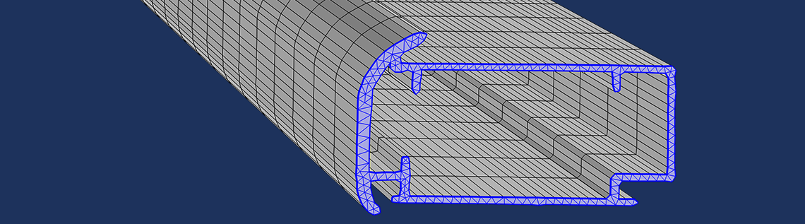
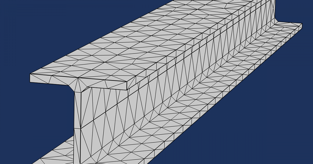
In the figure below, you can see a few of the different steps involved in order to create a swept mesh based on a photo of a profile that was drawn with a black marker. In this case, the 3D model was created by extruding the image-based 2D geometry.

An imported photo (taken with a smartphone) of a profile drawn with a black marker with an overlaid contour plot (thin green line).

The solid geometry profile resulting from deleting a few extraneous domains that is created in the conversion from an image to a geometry.

A swept mesh based on the black marker profile.
Enabling the Image to Curve Add-In
First, enable the Image to Curve add-in from the Add-in Libraries by going to the Developer tab in the Model Builder and clicking Add-in Libraries.
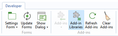
The Add-in Libraries button.
From the list, select the check boxes for the Image to Curve add-in to enable it.
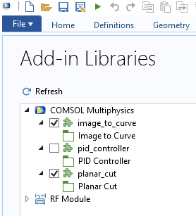
The Add-in Libraries window.
The Image to Curve add-in will then display when you click the Add-ins button, located on the Developer tab.
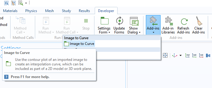
Accessing an add-in from the Developer tab.
The Image to Curve Settings Window
The Settings window for the Image to Curve add-in is shown below. It has five toolbar buttons at the top and five different sections with various settings.
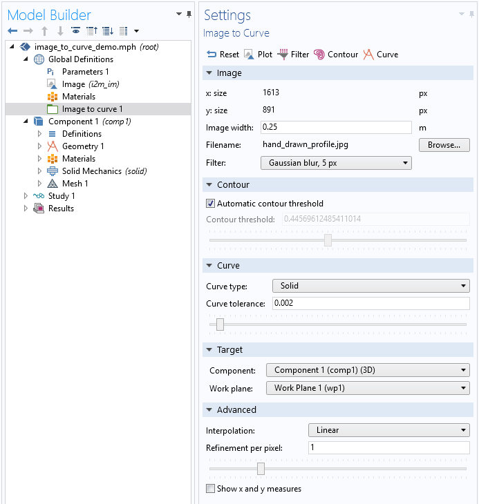
The Image to Curve Settings window.
Use the toolbar at the top of the Settings window to navigate between the different steps.
![]()
The toolbar buttons of the Image to Curve add-in.
The Image to Curve add-in buttons include:
- Reset
- Resets all values to factory settings
- Plot
- Renders the original imported image without any filter
- Filter
- Renders the filtered image using the Filter specified in the Image section
- Contour
- Plots image contours using threshold settings from the Contour section
- Curve
- Creates an Interpolation Curve node in a 2D Geometry sequence or a 3D Work Plane
- The curve interpolation tolerance can be adjusted in the Curve section
The sections for the Image to Curve add-in include:
- Image
- Contour
- Curve
- Target
- Advanced
The different sections are described in detail below.
Image Section
To import an image, in the Image section of the Settings window for the add-in, click the Browse button. This opens a file browser where you can select an image for import.
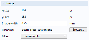
The Image section.
The image can, for example, be a photo of an object or a drawing. The supported image formats are .png, .jpg, .jpeg, .bmp, and .gif. In order to create a good-quality geometry, the image should preferably be a dark shape on a lighter background or a light shape on a darker background. When imported, a color image is always converted into a grayscale image.
After import, the Image section will display information on the image size in pixels (x size and y size), the image width in terms of the current length unit as determined by the Geometry node, the Filename, and the Filter used to process the image.
By changing the Image width value, you can adjust the dimensions of the final geometry. This could also be changed later by adding a Scale feature node to the Geometry sequence. The Filter options include a few blur and sharpening filters, as shown in the figure below.
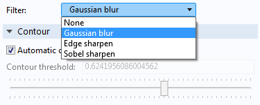
The Filter settings.
Use these filters to reduce noise (blur) or enhance edges (sharpen) in the imported image. Changing the filter will change the shape of the curve extracted from the image. The default is a Gaussian blur filter. If needed, use a dedicated image processing software to further process the image before import. Click the Plot or Filter button in the toolbar to render the original or filtered image, respectively.
Contour Section
By default, contour curves are automatically placed at an approximate average threshold level with respect to the pixel intensity level in the filtered image. To manually control the Contour threshold, clear the Automatic contour threshold check box.
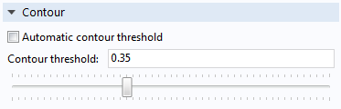
The Contour section.
Click the Contour button in the toolbar to visualize the contour curves and image, as shown in the figure below in the case of an imported image of an I-beam profile.

Image contours (in green) for an image of an I-beam.
To inspect the pixel values, in the Image to Curve plot group, select the Surface node, and click in the Graphics window. The pixel values and coordinates are displayed in an Evaluation 2D table, as shown in the figure below.
![]()
An image of an I-beam with pixel grayscale values displayed in a table.
Curve Section
Click the Curve button in the toolbar to generate an Interpolation Curve node in a 2D Geometry sequence or a 3D Work Plane. By default, the Curve type is set to Open, but you can change this to Closed or Solid. The Curve tolerance setting determines how closely the curve should approximate the contour curves.

The Curve section.
The figure below shows the I-beam example, using Solid for the Curve type and a Curve tolerance of 0.0.

A 2D solid geometry based on the image contours from the I-beam image.
Target Section
In the Target section, you can specify the Geometry sequence for which the Interpolation Curve node should be created. You can specify the model Component and, in the 3D case, you can also specify the Work Plane.
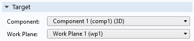
The Target section.
Advanced Section
In the Advanced section, you can change the interpolation method used to visualize the image. Select between Linear and Nearest neighbor interpolation. The Refinement per pixel setting determines the number of grid cells per pixel used to represent the image. A value lower than 1.0 means the grid used to represent the image has fewer interpolation points than the number of pixels in the image. A value greater than 1.0 means that the grid will oversample the image.
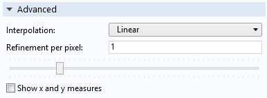
The Advanced section.
The Show x and y measures check box controls visualization of the dimensions of the contour curves.

Annotation of dimensions of the contour curve.
Finding Help
To view the dynamic help associated with the add-in, click the Image to curve node in the model tree and then click the question mark icon in the upper-right corner of the COMSOL Desktop® user interface (just like you would do to get the documentation for other Settings windows).
Examples Showing How to Convert Images to Geometry Models
You can download the example models and the accompanying images shown above.
The example image_to_curve_h_beam.mph contains a simple structural analysis with a distributed load, as shown in the figures below.

A distributed load on an H-beam based on an extruded image-based geometry.

The von Mises stress in an H-beam.
The example hand_drawn_image_geometry_and_mesh.mph contains the geometry and swept mesh of the black marker profile described in the beginning of this post. In addition to showing how to use the Image to Curve add-in, it demonstrates how to remove a few extraneous domains that are created in the conversion from an image to a geometry.
Note that you can keep working with the resulting 2D or 3D extruded geometry by using all of the geometry modeling features available: combine with additional geometry parts, drill holes, etc. The mesh in the above examples are swept meshes, but you can just as well use an unstructured tetrahedral or triangular mesh.
Additional Resources
To learn how this add-in was created, you can view, and even modify, its Application Builder settings by loading the corresponding MPH-file from the COMSOL installation directory. For a typical installation in the Windows® operating system, the file is located at:
C:\Program Files\COMSOL\COMSOL55\Multiphysics\addins\COMSOL_Multiphysics\image_to_curve.mph
To learn more about creating add-ins and applications in general using the Application Builder, see the:
You can also access these documents in your COMSOL Multiphysics installation through the Help and Documentation tools.

Comments (8)
Yi Luo
February 24, 2020Thank you very much! It is very useful.
Ekkehard Holzbecher
November 6, 2021Dear Bjorn
Thanks a lot for your always helpful explanations.
I have an observation concerning the ‘image to curve’ app, which seems strange to me. Once it is added to the Model Builder, it doesn’t appear in the add-in list anymore. Moreover the node in the model tree cannot be duplicated, although the automatic naming ‘image to curve 1’ suggests, it could be used several times. What can I do, if I want want to use the app twice or more?
BRs Ekkehard (from Oman)
Bjorn Sjodin
November 8, 2021 COMSOL EmployeeHi Ekkehard,
You are welcome!
Your observation is correct. This add-in is a so called “singleton” add-in and can only exist in one copy in the Model Builder. We might generalize this add-in in a future version. In the current version, you would need to open several COMSOL sessions and use file export/import to work with multiple image files simultaneously. One image file per session.
Best regards,
Bjorn
Ekkehard Holzbecher
November 16, 2021Thanks Bjorn.
After some trial and error I got it working.
Best regards, Ekkehard
Garshasp Keyvan Sarkon
February 28, 2022Greetings dear Bjorn, I uploaded an image and turned it into a curve, the only problem is I can’t change the X and Y dimensions of my Image that is tuned into solid geometry, there is an option for the determination of the width of the image, but the X and Y dimensions can not be modified? how can I fix this issue?
Thanks in advance.
Bjorn Sjodin
February 28, 2022 COMSOL EmployeeHi Garshasp,
In the add-in, you can change the Image width. The other option is to use the tools under the Geometry node (in the Model Builder) to move, scale, and rotate the resulting curve.
Best regards,
Bjorn
malcolm anderson
August 19, 2023Can I find more info about it in google?
malcolm anderson
August 19, 2023this is very interesting