

Journal bearings are lubricated components that support a rotating shaft. Cavitation affects the performance of these bearings and must be considered during the design stage. Here, I’ll explain what journal bearings are and why predicting cavitation is important, as well as share an industry example with you.
What Are Journal Bearings?
Journal bearings are typically used to support a rotating shaft. They are made of two parts: a shaft (or journal) rotating in a fixed bearing. To reduce the friction and wear between the fixed bearing and the rotating shaft, the thin gap between these two parts is filled with a viscous fluid, such as oil, thus avoiding surface-to-surface contact. This lubricant also damps undesirable mechanical vibrations. This thin layer of fluid is referred to as the lubrication layer. Its thickness is ideally in the realm of thousandths to hundredths of a millimeter.
About Cavitation
Because of the loads applied to the bearing and the shaft, the lubrication layer’s thickness is not constant, and neither is the flow pressure. When the flow pressure drops below the ambient pressure, the air and other gases dissolved within the lubricant are released. This phenomenon, characteristic of loaded bearings, is known as cavitation or gaseous cavitation.
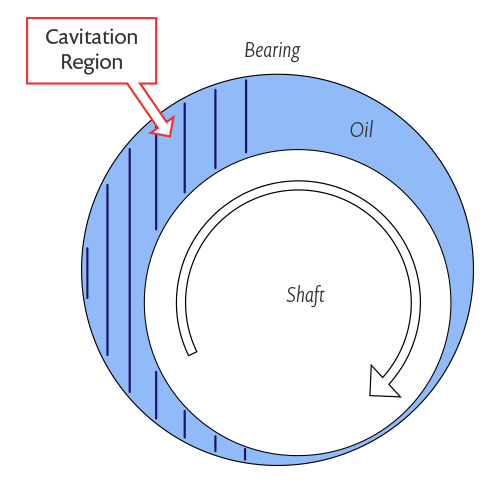
Schematic of a journal bearing.
In some cases involving high-frequency varying loads, as in internal combustion engines, the pressure might drop below the oil vapor pressure (which is lower than the ambient pressure). In this case, bubbles are formed by rapid evaporation/boiling of the oil. This phenomenon is known as vapor cavitation.
Being able to predict the onset and extent of cavitation in the lubrication layer is important for two main reasons:
- The onset and extent of gaseous cavitation in a journal bearing determines the load that can be applied to the bearing.
- The implosion of vapor cavitation bubbles creates some serious damage to the journal and bearing surfaces.
Predicting Cavitation
The pressure of the lubricant can be computed from the Reynolds equation. This equation is not solved in the three-dimensional fluid domain between the bearing and the shaft, but instead on a two-dimensional surface within the gap.
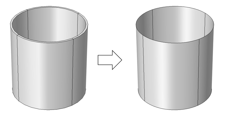
Therefore, the clearance between the shaft and the bearing is not represented in the geometry, where the two parts are in contact. This “lower dimension” approach drastically reduces both the CPU usage and memory load during the model resolution. In the COMSOL Multiphysics simulation software, the Reynolds equation has been modified to account for gaseous cavitation effects.
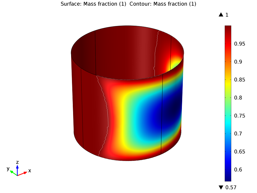
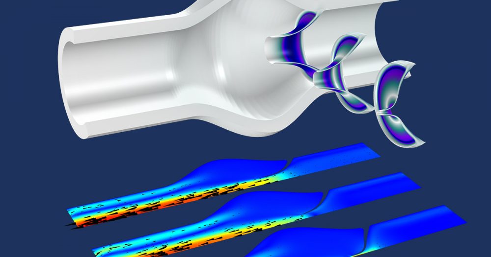
This tutorial from our Model Gallery predicts the onset and extent of cavitation in the lubrication layer of a journal bearing. The color represents the mass fraction of the lubricant in the cavitation region. The white contour shows the outline of the region of cavitation. (This model requires COMSOL Multiphysics and the CFD Module.)
Industry Example: Dynamics of Rotors on Hydrodynamic Bearings
At the COMSOL Conference 2013 Rotterdam, Rob Eling from Mitsubishi Turbocharger & Engine Europe presented his work where he used COMSOL Multiphysics and the thin film physics interface to evaluate the risk of rotor instability caused by the interaction between the rotor and the bearings in a turbocharger.
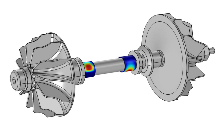
Image Credit: R. Eling, Mitsubishi Turbocharger & Engine Europe, Almere, The Netherlands.
This highly nonlinear analysis involves two main components:
- A flexible shaft (shown in gray in the above plot) linking both sides of the turbocharger.
- Two individual hydrodynamic bearings (shown in colors in the above plot).
The coupled analysis of this problem enables the prediction of the following critical performance criteria:
- The stability of the rotor to ensure safe operation under all loading conditions.
- The response of the rotor to unbalanced loads to prevent wear and noise issues.
- The friction losses in the bearings.
Because of the complexity of the model, the problem was tackled in three steps.
Step 1
The first step involved performing an analysis of the rotor dynamics (i.e., the structural mechanics problem without considering the bearings):
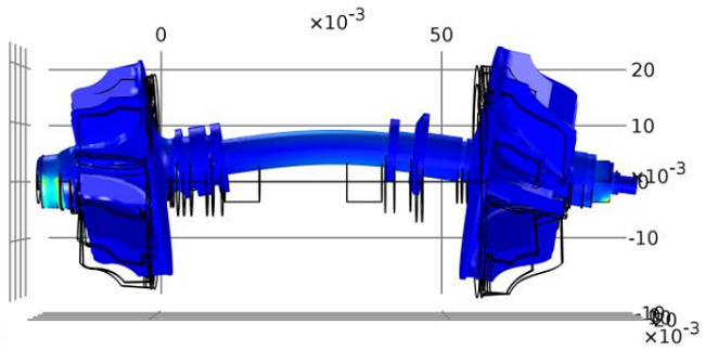
Image Credit: R. Eling, Mitsubishi Turbocharger & Engine Europe, Almere, The Netherlands.
Step 2
In the second step, he performed an analysis of the hydrodynamic bearings:
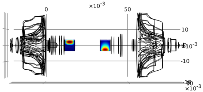
Image Credit: R. Eling, Mitsubishi Turbocharger & Engine Europe, Almere, The Netherlands.
Step 3
Finally, he ran an analysis of the coupled rotor-bearing system:
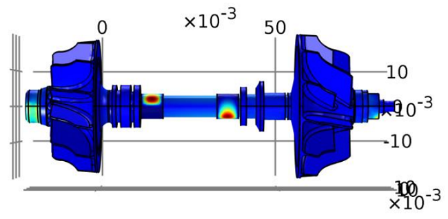
Image Credit: R. Eling, Mitsubishi Turbocharger & Engine Europe, Almere, The Netherlands.
Eling ran simulations over the full operating range and showed the presence of many interesting — and potentially dangerous! — self-induced vibrations of the system due to the fluid-structure interactions between the rotor and the bearings.
Additional Resources
For more information on the research shown here, please refer to Eling’s paper “Dynamics of Rotors on Hydrodynamic Bearings“, as presented at the COMSOL Conference 2013 in Rotterdam. If you have any questions, please contact your local technical support team.

Comments (0)