

The CAD Import Module, Design Module, and the LiveLink™ products for CAD include tools for repairing and preparing a geometry for simulation. They are powerful additions to the geometric modeling capabilities of the COMSOL Multiphysics® software. Let’s discuss how these tools work and when to apply them.
A Brief History on the Use of CAD
Computer-aided design (CAD) has a long history that almost dates back to the very first electronic computers. For most companies, the original motivation behind adopting CAD software was to automate a product’s design, documentation, and manufacturing process in order to clearly and effectively communicate engineers’ designs to production facilities.
Before 3D CAD models, products were created from 2D designs that came in the form of 2D drawings. Later on, designers started to generate 3D models based on 2D drawings. CAD designs have played an important role in a product’s life cycle over the years.
Today, 3D CAD models can be found in a wide range of documents and applications, spanning from service manuals to analyses. Some organizations have gravitated toward completely eliminating the production and distribution of traditional 2D drawings. With the elimination of 2D drawings, 3D CAD models are a product’s sole information source, which forces these models to streamline even more processes in a product’s life cycle.
Preparing a CAD Design for Analysis
It can be a challenging task to use the same 3D data set for the various stages in a product’s life cycle. This is especially true for finite element analysis, as it typically requires a very-high-quality 3D geometry.
For example, to create a volume mesh for a component, we would need a watertight surface geometry that can be made into a solid with an interior region. Usually, this is something we don’t need to worry about, because the imported geometric data contains the 3D solid object and the mesh is automatically created.
However, due to the complexity of the design and/or repeated translations from one CAD format to another, data can sometimes be lost or inaccurate, which can result in incomplete surfaces with gaps. In this scenario, we would need to rely on either automatic repair during the import process or use the provided repair tools, which are described in further detail below.
Using Different Representations of the Same Design
Various types of analyses require widely different representations of the same design.
Before starting a COMSOL Multiphysics model, it is important to determine the level of detail necessary to obtain desired results. A good understanding of the scope of the study and the involved physics greatly helps in determining the most efficient path to an analysis’ appropriate geometry.
For instance, to receive a detailed analysis of a bolt thread’s load-carrying capacity, you would use a geometric representation of the bolt that differs from the one you’d use for a heat conduction simulation in a large assembly that contains many bolted connections.
In the first scenario, a detailed representation of the bolt thread is important, while in the second scenario, a simple cylinder that fills the bolt holes would suffice. Depending on how the bolt is represented in the CAD files, you would need to either simplify its geometry or add details to it in order to run the simulation.
We often face situations where some components need simplification (also referred to as defeaturing), more detail, or repair before generating the mesh.
To understand the tools available for the repair and defeaturing of a geometry, it helps to factor in the size and nature of the removed details.
How the Size of Geometric Details Affects the Analysis
In most cases, details such as fillets, chamfers, holes, and fasteners are important for a product’s functionality. However, they can be deleted from the geometry depending on the scope of the analysis. When we remove these features, a considerably sized gap, or “wound”, will remain. This gap needs to be covered by a replacement surface so that we can restore a solid object, allowing us to create a volume mesh.
When using the defeaturing tools in COMSOL Multiphysics, gaps are automatically covered as part of the operation (e.g., extending adjacent faces over the gap). There is, of course, always the possibility of manually deleting faces and drawing a new geometry to cover the gaps.
Many of the geometric features that we would like to remove are small enough that they can be deleted by collapsing them into a point or line segment. This can be done without causing a noticeable change to the surrounding faces, which is usually a lot easier than figuring out how to construct a larger face to cover a gap.
Very small surface patches are often introduced into a CAD model with a complex shape to ensure a sufficiently smooth surface. Sometimes, the CAD model can also contain fillets of a very small radius or the placement of a larger feature, which leaves a very thin sliver in the geometry.
Importing and Repairing CAD Geometries in COMSOL Multiphysics®
The smaller the feature that is to be deleted, the easier it is to cover the resulting gap without causing unexpected changes in the surrounding geometry. Collapsing a very small edge or face into a point only necessitates a very small local change to the neighboring faces and edges. The same holds true for collapsing a sliver into an edge.
These two operations are, in fact, part of a whole range of repair and cleaning operations, which are done by default when importing a CAD file. The CAD file’s model contains a collection of the mathematical descriptions of the surfaces and information about how they are connected.
Since the various CAD formats represent surfaces differently, there is always a possibility that problems will be introduced when going from one format to another. This can happen when exporting and importing CAD files. An import algorithm includes a repair functionality that can find and fix a whole range of problems, such as incorrect or missing connectivity information, erroneous shape information, tolerance issues, and more.
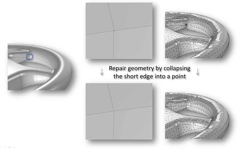
During import, the repair algorithm detects and deletes short edges.
Controlling Surfaces During Import
During import, you can control how surfaces are treated. By default, COMSOL Multiphysics tries to knit, or stitch, surfaces together to form a solid object. While the software does this, the code tries to cover any gaps by creating new surfaces. For large gaps, this could lead to unexpected results. If this happens, change the setting to import surfaces without stitching or forming solids. You can then draw new surfaces in the COMSOL® software to cover the gaps.
For most cases, the default import tolerance does not need modification, but it is good to know that it can be changed if you’re importing very large or small objects. In the former case, the tolerance could be too small, leaving many slight details and other errors in the geometry. In the latter case, the tolerance could be too large, causing the loss of important details.
Defeaturing and Repairing CAD Designs
The automatic Repair and Knit to Solid operations, performed during import, are also separately available in the user interface of the COMSOL® software. You will find these operations in the Geometry toolbar under Defeaturing and Repair when you use the CAD Import Module, Design Module, or any of the LiveLink™ products for CAD.
These tools come in handy when importing an assembly that contains both larger and smaller components and when the same tolerance setting is not suitable for all components.
To do this, first import the assembly using a tolerance setting tuned for the smallest component. After the import, run the Repair and Knit to Solid tools with a larger tolerance to fix the bigger components. The Knit to Solid tool can heal gaps between faces and, when possible, make a solid object. It is good to use these tools with caution as we increase the tolerance, since they might result in unexpected changes to the geometry.
Deleting Smaller Details
The Repair tool finds and deletes faces and edges that are smaller than the repair tolerance. To gain precise control over what is deleted, we can use the tools to detect and delete short edges, spikes, slivers, and small faces. These tools work well for relatively small features that can be collapsed to an edge or a point.
During this process, the curvature of surrounding faces is slightly modified to allow for the change in geometry. This is why these tools should not be used to delete large faces. For some simulations, it can be important that the original surface curvature of the geometry is kept, in which case it is better to use the virtual geometry operations for defeaturing the geometry.
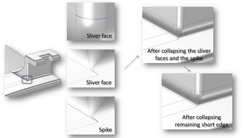
Deleting sliver faces, spikes, and short edges by collapsing them into edges and points.
In the image above, the highlighted region of the fastener detail contains two sliver faces and a spike. These can be detected and removed by using the Delete Sliver Faces and Delete Spikes tools. While a sliver face is a face with a high aspect ratio, a spike is a region with a high aspect ratio inside a face. As illustrated in the schematic above, small features like these often occur where several fillets of different radii meet. After deleting the sliver faces and the spike, a short edge remains that can also be detected and deleted by using the Delete Short Edges tool.
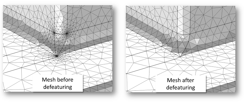
The mesh for the highlighted region of the fastener before and after defeaturing.
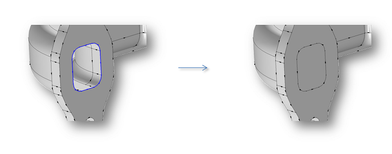
Deleting Larger Details
The method of removing features works well for small features only. To close a gap after a larger detail, other methods are needed. The Delete Fillets, Replace Faces, and Delete Holes tools allow you to select the faces you wish to delete. These tools close the resulting gaps by extending or shrinking the surrounding faces. For this to succeed, it is important that there is enough information in the adjacent faces to cover the gap. The delete operations also have an option to create a cover for the gap, based on its edges.
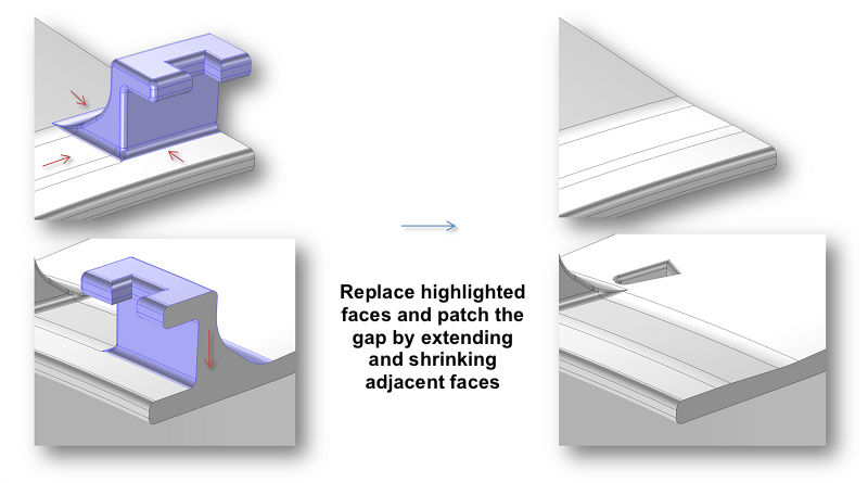
A large detail is deleted by using the Replace Faces tool.
Creating Features
Up until now, we have looked at the tools to repair and defeature an imported geometry. With the Detach Faces tool, which is also found under the Defeaturing and Repair menu, we can detach a set of faces into a new solid object. This can be very useful if we’d like to assign different material properties to a region of the imported object (the fastener detail highlighted in the previous figure, for example).
Using this tool, a through hole can be detached into a solid object by selecting its walls. Another method for creating domains for flow regions through a solid object is to use the Cap Faces tool, which can be found in the Defeaturing and Repair menu as well.
A new domain is created for the hole with the Cap Faces tool.
The inputs for this tool include the edge loops around the cavity’s inlets and outlets or the through hole. Based on the edges, cover surfaces are constructed to cap the holes, thus creating a new domain in the solid. Given that there is an appropriate set of edges around a solid, this tool can also be applied to create a new surface that partitions the solid into different regions.
Further Reading
Learn more about using features for geometry and CAD on the blog:


Comments (0)