support@comsol.com
LiveLink™ for PTC Creo Parametric™ Updates
For users of LiveLink™ for PTC Creo Parametric™, COMSOL Multiphysics® version 6.2 includes improved automatic naming of geometry objects and a new Component Selection window to select and deselect CAD components for synchronization. Read about these updates and more below.
Improved Naming of Geometry Objects
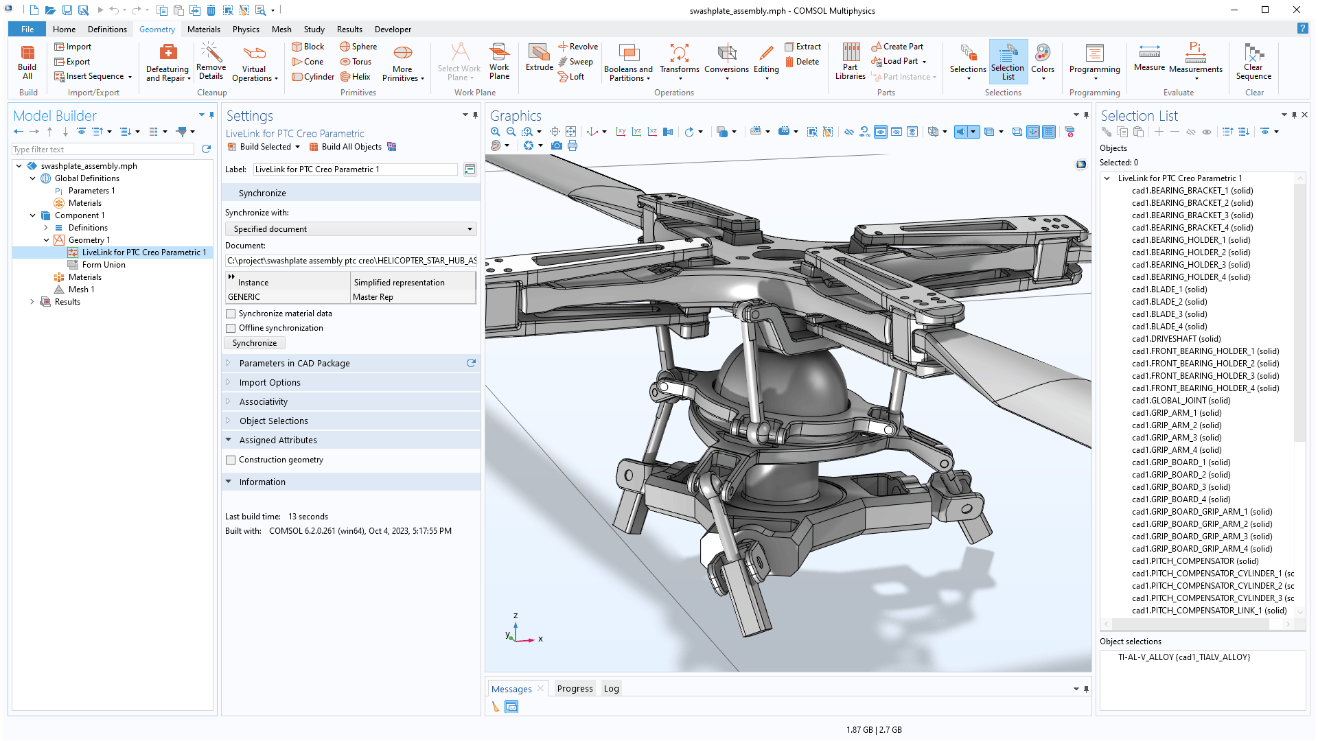
When synchronizing CAD assemblies between the PTC Creo Parametric™ and COMSOL Multiphysics®, the names of the synchronized objects in the COMSOL model are now derived from the component names in the CAD assembly. The object names can be viewed within the Selection List window, making it much easier to recognize and interact with the assembly parts after synchronization.
Improved Selection of Components
A Component Selection window is now available in the PTC Creo Parametric™ user interface for selecting assembly components for synchronization with COMSOL Multiphysics®. Previously, turning off the visibility of components prevented them from being synchronized. Using the new Component Selection window provides the ability to control which assembly components to synchronize, without the need to change the visibility of the component in the CAD software user interface.
Improved Edge Selection for Cap Faces
The Cap Faces feature now includes a new Group adjacent edges check box in the Settings window. This feature can be enabled to automatically select all edges in a loop when clicking on an edge.
Updated CAD File Import
The CAD file import functionality has been extended to support the most recent versions of the supported file formats. Additionally, importing the SOLIDWORKS® file format is now available on a supported Linux® operating system with an Intel® 64-bit processor. A current list of supported CAD file formats can be viewed within the Read from File section of the CAD specification chart.